Today’s journey back in time is going to take us to 1993 in post-communist Bulgaria. It was only a few years after one day at school we were told to stop addressing the teachers as “comrade” and start using the “Mr.” and “Mrs.” honorifics.
I was going to school, and my computer was a Bulgarian clone of the IBM XT. I think at some point I had 20MB hard drive but I am not sure about that. Doing what many of the lucky generations did, I was hanging out at computer clubs while one day somebody challenged me to write a computer program that generates crosswords.
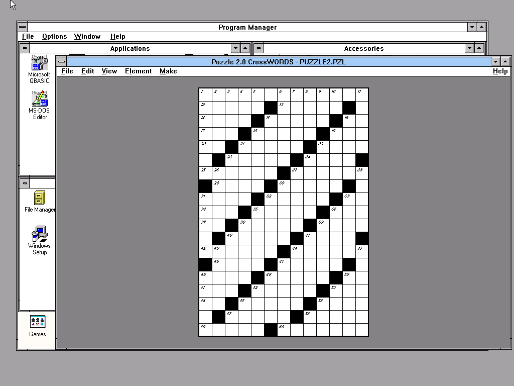
So I did. Today I dug it up, compiled it, and put the sources on my GitLab server, for no other reason but to entertain the reader. Sadly, I lost the knowledge of Bulgarian Cyrillic code tables, so there is a nice little project for when I have time.
I remember that CPU power was same expensive during the years and I often left friends’ PCs with the state-of-the-art blazing fast at the time 80486 Intel process overnight to generate the crosswords that I was selling to the local Varna newspapers. It would take an hour to make a moderately small crossword puzzle. I ran the program yesterday, and it took a few seconds to fill the grid of the crossword shown above.
At the time I didn’t know that the problem is NP-hard, but I designed my algorithm to be sound and complete and I am a bit proud of my teenage self given that the OpenAIs and Anthropics of the Mecca seem to have forgotten this exact type of human knowledge. I guess Altman or Amodei were too busy fraternizing to take CS 101 or logic.
Expect next week: more on using real computer science and algorithms for EDA and hopefully on Friday VmWare images generating crossword puzzles with Windows 3.1 and a small digression to a clone of Wordle.
Ceterum censeo slopem esse delendam.
(Cato the Elder ended every speech in the Roman Senate with “Carthage must be destroyed” — regardless of the topic. This is that, but for AI slop.)
Bitcoin miners are liquidating their holdings to pivot into AI hosting. The machines that wasted electricity producing imaginary money will now waste it producing imaginary intelligence. Anthropic has secured 3.5 gigawatts of compute — the consumption of three and a half million households — to serve language models.
GCC compiles the entire Linux kernel in fifteen minutes on a single machine drawing 200 watts. Fifty watt-hours. A light bulb left on for an afternoon. It manages this because it is not guessing. It has a grammar, a type system, and an optimisation pipeline where every transformation preserves semantics. There is no temperature parameter. There is no “try again and hope.”
A compiler’s cost is \(O(n \log n)\) in the size of the input. A language model’s cost is \(O(n \cdot d)\) where \(d\) is the dimensionality of a model that cannot tell you whether the answer is correct. When the task has a formal specification, you do not need gigawatts. You need a parser.
I have been writing parsers for twenty years. Today I started improving the one that matters most: the circuit description language at the heart of llogic, qbf-designer, and the formal methods toolchain I am building at Llama Logic.
My first encounter with a compiler was at Zend Technologies in Ramat Gan in 2000. I was twenty-two, fresh off the plane from Bulgaria, and I did not know what a parser was. Zend built the PHP language engine. I watched a small team turn a grammar into a working language that ran half the web. I did not understand how.
A few years later, at Delft, I read the Dragon Book and took the compiler construction course of Koen Langendoen. We became friends over my many years at the university. That course turned out to be one of the most useful things I have ever learned. It is the skill that lets me write software that works — not approximately, not statistically, not when the vibes are right, but deterministically, on all inputs, by construction.
It is also how I got into diagnosis. At the end of my master’s I went to Koen and asked for a Ph.D. position in compiler construction. He told me “compilers are passé” — but I could go work with Arjan J.C. van Gemund doing diagnostics. Arjan has since retired north to compose music, which is a better use of a fine mind than supervising Ph.D. students, though he was good at both. They needed a compiler for LyDiA, the diagnostic modelling language. So I built one. Then I built many more. Every research system I have worked on since — LyDiA, the DXC framework at NASA Ames, the synthesis tools at PARC, and now llogic — has a parser at its core. The compiler is never the point. The compiler is always the point.
A domain-specific language is a small language built for one job. SQL is a DSL for databases. Regular expressions are a DSL for pattern matching. Makefiles are a DSL for build dependencies. You do not write an operating system in SQL. You do not query a database with a Makefile. The language fits the problem, and because it fits, it can enforce constraints that a general-purpose language cannot.
This is the point that the vibe-coding movement misses entirely. A grammar is not a convenience. It is a contract. When I write a parser for a circuit description language, the grammar specifies exactly what constitutes a valid circuit. If you misspell a gate type, the parser rejects your input. If you connect an output to a nonexistent signal, the parser tells you. If you instantiate a module that does not exist, you get an error message with a line number — not a plausible-looking circuit that silently computes the wrong function.
This is what determinism means in practice. The parser either accepts or rejects. There is no 95% confidence. There is no temperature. The same input produces the same result every time, on every machine, for every user. A QBF solver receiving a malformed netlist will produce garbage. A diagnosis engine receiving an inconsistent model will compute meaningless results. The parser is the gate that keeps garbage out. It costs milliwatts. It works.
There is a second reason, less often discussed. Humans need to read these things. An engineer debugging a faulty adder needs to look at the circuit description and understand it. A reviewer verifying a synthesis result needs to confirm that the specification matches the intent. This is not a machine-to-machine format. It is a language — with the same design obligations as any language: clarity, consistency, and the ability to say exactly what you mean and nothing else.
The circuit DSL in llogic had outgrown its grammar. The new format adds modules, arrays, imports, and arbitrary nesting. A full adder, from primitives to a 4-bit module with array slicing:
# 4-bit ripple carry adder

import "std_logic.circ"

module half_adder(input a, b; output s, c):
    x: s = xor(a, b)
    a: c = and(a, b)
end

module full_adder(input a, b, ci; output s, co):
    wire f, p, q

    inst half_adder ha1(a=a, b=b, s=f, c=p)
    inst half_adder ha2(a=ci, b=f, s=s, c=q)
    o: co = or(p, q)
end

module adder2(input a[2], b[2], ci; output s[2], co):
    wire c0

    inst full_adder bit0(a=a[0], b=b[0], ci=ci, s=s[0], co=c0)
    inst full_adder bit1(a=a[1], b=b[1], ci=c0, s=s[1], co=co)
end

module adder4(input a[4], b[4], ci; output s[4], co):
    wire cm

    inst adder2 lo(a=a[0:1], b=b[0:1], ci=ci, s=s[0:1], co=cm)
    inst adder2 hi(a=a[2:3], b=b[2:3], ci=cm, s=s[2:3], co=co)
end
Four levels of nesting. Modules, arrays, slices, named connections. The flattener — a recursive tree walk, the same algorithm I used in LyDiA for system descriptions — traverses the instantiation tree and emits the flat netlist the solver has always consumed. The hierarchy is for the engineer. The solver does not know it exists.
Sequential circuits work the same way. A 4-bit serial adder with synchronous reset:
A dff with one argument is a plain register. Two arguments: synchronous reset. This maps directly to the standard Verilog template always @(posedge clk) if (rst) q <= 0; else q <= d; — making translation between the two languages mechanical.
So why not just use Verilog?
Because Verilog is a simulation language that has been coerced into serving as a synthesis input. A synthesis tool reads an always block, pattern-matches the sensitivity list, and infers what is a register and what is combinational logic. The engineer writes behaviour and hopes the tool’s heuristics match their intent. In llogic, a dff is a dff. An and is an and. There is no inference. The circuit says what it is.
This matters for formal methods. Diagnosis requires knowing exactly what components exist. Synthesis requires a precise specification of the design space. Neither tolerates a language that hides structure behind inference rules. Verilog is the right language for RTL designers who want to describe behaviour and let tools figure out the structure. Llogic is the right language when the structure is the point.
The parser, AST, and flattener should take a few days. When they are done I will update the llogic repository on the feature/hierarchical-dsl branch.
Three and a half million households’ worth of electricity to serve a model that cannot tell whether it is thinking deeply or not. Fifty watt-hours to compile a kernel. Considerably less to parse a circuit. The tools that work have always been quiet, small, and correct. The software will continue to not hallucinate.
Ceterum censeo slopem esse delendam.
(Cato the Elder ended every speech in the Roman Senate with “Carthage must be destroyed” — regardless of the topic. This is that, but for AI slop.)
It is Friday. KPMG, the consultancy behemoth that delivers business Venn diagrams for outrageous prices, informs us that 70 percent of UK business leaders will keep spending on AI even when they can’t prove it does anything — the consultancy helpfully suggests we stop calling it “investment” and start calling it a “strategic enabler for enterprise-wide transformation,” which is the corporate equivalent of renaming a hole in the ground a “subterranean opportunity space.”
Meanwhile, OpenAI has put Stargate UK on ice, citing the cost of electricity and the regulatory environment, mere months after announcing it during a Trump state visit — one assumes the due diligence was conducted with the same rigour as the naming convention.
AMD’s AI director reports that Claude Code has become “dumber and lazier” since February, based on analysis of 6,852 sessions and 234,760 tool calls, which is the most thorough performance review any AI has received and rather more than most human employees get. One notes that the AWS CEO, asked whether AI is overhyped, described the question as “one of the funnier questions I get” and then asked a room full of people who had each paid $4,000 to attend an AI conference whether they believed in AI. Asking turkeys to vote on Christmas, as it were.
In this climate of expensive credulity naïveté, I thought we might spend a Friday doing something that we do on Fridays: looking backwards. Reverse engineering — the art of taking something apart to understand what it does — is the intellectual opposite of the current AI approach to technology, which is to build something enormous, declare it transformative, and hope nobody asks what it actually computes.
The Правец (Pravetz): Bulgaria’s Apple II, Give or Take an Iron Curtain
I grew up using Правец (Pravetz) computers — forgive the Cyrillic, but we Bulgarians invented the alphabet, even though half the Slavic world claims the credit, and besides, it makes any noun look like classified military hardware. Every Bulgarian of a certain age used one. The Правец 82 was the machine in my school, with its yellow plastic case, black keyboard, red RESET key, and the unmistakable aura of a computer that had been reverse-engineered from a capitalist original by engineers who had never seen Cupertino and didn’t need to.
My first encounter with a personal computer was typing in a BASIC program that drew Lissajous figures in hi-res graphics. I was in the fourth grade. It was 1987. But I am digressing.
IMKO-1 PC
The story of the Bulgarian computer is worth telling properly. In 1979, engineer Ivan Marangozov at the Institute of Technical Cybernetics and Robotics (ИТКР) in Sofia built the IMKO-1 — the first Bulgarian personal computer. It was a clone of the Apple II, and “clone” is doing some diplomatic heavy lifting here: the ROM was identical, the schematics were identical, the 6502 CPU ran at the same 1 MHz. The differences were a metal case that could double as ballast, a linear power supply heavy enough to qualify as exercise equipment, and the replacement of lowercase Latin with uppercase Cyrillic — because behind the Iron Curtain, you didn’t do lowercase. The keyboard used 7 bits for character codes, so Cyrillic overlapped with Latin lowercase. A limitation, but also an engineering decision that had a certain brutal elegance: you get one alphabet at a time, comrade, and you will type in capitals.
The rumours of how this was accomplished are better than the facts. The Bulgarian intelligence services allegedly sent operatives to procure Apple IIs from the West — less James Bond, more cartoon characters getting drunk on capitalist Coca-Cola while trying to buy a computer with a heavy accent and a suitcase full of leva (the Bulgarian currency, not then known for its convertibility). More interesting is what happened next: an institute in Sofia was reportedly tasked with decapping the ICs, lifting the netlists under a microscope, and reproducing them with socialist lithography — the equipment for which was probably lifted from the Dutch. The reasonable question is why arguably clever people went through all of this when designing an ALU from scratch is not that difficult, but we will leave this armchair philosophy question to the LLMs. They have the confidence for it, if not the answer.
Today, people do this sort of thing voluntarily and for fun. The 6502.org community hosts dozens of homebrew computer projects — enthusiasts building 6502-based machines from scratch on breadboards, complete with VGA output and SD card storage, using parts that are still in production. The MOnSter 6502 takes it further: a fully functional 6502 processor built from 3,218 discrete transistors on a circuit board the size of a dinner plate, with LEDs showing the state of every register. What the Bulgarian state did with an institute and a five-year plan, hobbyists now do in garages on weekends.
Marangozov was, depending on your perspective, either rightfully accused of cloning the Apple II or laudably credited with delivering computing to an entire country that couldn’t buy one. The truth is both, and neither is shameful. Apple II schematics were published. Steve Wozniak intended the design to be understandable. What Marangozov and his team did was take a published design, source the components (Bulgarian and Soviet clones of American chips — clones all the way down), adapt the character set, and manufacture hundreds of thousands of units that shipped to every school and scientific institute in the Eastern Bloc. By the mid-1980s, Bulgaria was producing 40 percent of the personal computers used in COMECON countries. Not bad for a country whose communist leader Todor Zhivkov — a peasant’s son turned printer’s apprentice who rose through the party ranks on the strength of Soviet patronage and the convenient absence of anyone more threatening — happened to have been born in the village that gave the computers their name. Правец was a hamlet of no consequence until Zhivkov turned it into a town by decree in the 1960s; by the 1980s it was assembling the flagship technology of the Eastern Bloc. One does not need a diagnostic engine to detect the fault in this particular circuit of patronage.
The later models improved substantially. The Правец 8M integrated a Z80 alongside the 6502, letting it run CP/M. The 8A was a proper Apple IIe clone with expandable memory. The military version had an integrated terminal design, because of course it did. There was even a Правец 8D, which broke ranks entirely — it was a clone of the British Oric Atmos, presumably because even Bulgarian engineers sometimes want variety.
The point is not that Bulgaria copied Apple. The point is that reverse engineering — understanding a design well enough to reproduce and adapt it — was how an entire generation of engineers learned computing. We didn’t have access to Stanford or MIT. We had schematics, soldering irons, and a cheerful disregard for intellectual property law that was, in fairness, philosophically consistent with the economic system. The Правец was my first computer. Everything I know about hardware starts there: with a 6502, 48 kilobytes of RAM, and a cassette recorder that worked when it felt like it.
Hayes and the ISCAS Circuits: What Were They For?
Now here is a story about reverse engineering that is less well-known outside the EDA community but is, in its own way, just as delightful.
The ISCAS-85 benchmarks are the standard test circuits for digital design research. If you work on test generation, fault diagnosis, synthesis, or timing analysis, you have used them. They were released by Franc Brglez and Hisashi Fujiwara in 1985 as a “neutral netlist of 10 combinational benchmark circuits” — gate-level descriptions of real circuits, stripped of context, for the research community to use as common benchmarks.
There was just one problem. Nobody told the research community what the circuits did.
For fourteen years, thousands of researchers ran experiments on c432, c499, c880, c1355, c2670, c3540, c5315, c6288, and c7552. They generated test patterns for them. They diagnosed faults in them. They timed them, synthesized them, mapped them to FPGAs. They published papers about them. And nobody — nobody — knew what these circuits were actually supposed to compute.
Then in 1999, Mark Hansen, Hakan Yalcin, and John P. Hayes at the University of Michigan did what should have been done from the start. They reverse-engineered the lot. Their paper, “Unveiling the ISCAS-85 Benchmarks: A Case Study in Reverse Engineering,” published in IEEE Design & Test, is a masterpiece of detective work. They took each gate-level netlist, partitioned it into standard RTL blocks, identified the function of each block, and reconstructed the high-level architecture. The methodology was elegantly practical: Hayes assigned each circuit to a PhD student. Cheap labour, and almost certainly cheaper per insight than an LLM.
The results were revelatory. c432 turned out to be a 27-channel interrupt controller. c880 was an 8-bit ALU. c6288 was a 16×16 multiplier. c7552 was a 32-bit adder/comparator. c499 and c1355 were both 32-bit single-error-correcting circuits — the same function, different implementations. These weren’t abstract mathematical constructs. They were real designs, ripped from real hardware, and for a decade and a half the research community had been studying them the way archaeologists study pottery shards: knowing the shape but not the purpose.
Hayes’s contribution is profound and under-appreciated. By recovering the behavioral specifications, he gave the community something it had never had: the ability to test at the functional level, to verify synthesis results against intended behaviour, to use hierarchical structure for more efficient test generation. The high-level models are still available, complete with annotated schematics and structural Verilog, and they remain useful tools nearly three decades later.
Why This Matters
There is a thread connecting the Правец, the ISCAS reversal, and the work I’ve been doing with LyDiA and qbf-designer.
Reverse engineering is synthesis in reverse. When Hayes looked at c6288 and deduced it was a multiplier, he was doing — by hand, with extraordinary patience — what a diagnostic engine does automatically: given a circuit and its behaviour, determine its function. When Marangozov looked at the Apple II and built the IMKO-1, he was doing technology transfer through structural analysis. And when Johan de Kleer described synthesis as “diagnosing a circuit into existence,” he was observing that the mathematical machinery is the same in both directions. Start with a broken specification (nothing works, every gate is “faulty”), and ask: what collection of “repairs” (gate placements) would make the circuit compute the desired function?
This is the ∃∀ structure I discussed in Diagnosing Circuits into Existence — the same quantifier alternation, the same miter-based equivalence checking, the same PSPACE-hard satisfaction problems. Diagnosis, synthesis, and reverse engineering are three faces of the same formal object. The only difference is which variables you fix and which you solve for.
The ISCAS-85 benchmarks are, incidentally, the circuits that LyDiA diagnoses. When I demonstrate model-based diagnosis on c432, I am diagnosing a 27-channel interrupt controller — I just didn’t know that for the first several years of my PhD. Thank you, Professor Hayes.
The Moral
The current approach to technology is to build something forward: throw compute at a model, train it on everything, and see what comes out. Reverse engineering goes the other way: take something that exists, understand its structure, and extract meaning. One approach requires billions of dollars and produces systems that cannot explain themselves. The other requires patience and produces understanding.
Bulgaria built a computer industry on reverse engineering. Hayes rebuilt the foundations of benchmark-driven EDA research by reversing fourteen-year-old circuits. I am building a company on the formal connection between taking circuits apart and putting them together.
None of this requires a strategic enabler for enterprise-wide transformation. It requires mathematics, a soldering iron, and the willingness to look at something carefully until you understand what it does.
Amazon’s weekly operations meeting in March reportedly focused on a “trend of incidents” characterised by “high blast radius” and “Gen-AI assisted changes.” The Financial Times, which saw the briefing note, reported that AI-generated code had been implicated in a series of outages — including one that took down Amazon’s entire e-commerce website for several hours. Amazon’s response was to deny the problem existed, which is the corporate equivalent of the AI itself: confidently wrong and hoping nobody checks. James Gosling, the creator of Java, who left AWS in 2024, was less diplomatic. He observed that the company’s AI-driven restructuring had “demolished” the teams responsible for infrastructure stability, and that the ROI analysis behind the decision was, in his words, “disastrously shortsighted.” One does not need a diagnostic engine to identify the fault here. A company replaced the engineers who understood its systems with a technology that does not, and the systems fell over. The circuit breaker that the AI removed — the one it classified as “redundant” — had been added after a previous outage. The AI could not distinguish a safety mechanism from dead code, because it had no model of the system. It had statistics. Statistics told it the breaker rarely fired. A model would have told it why.
This is the difference between machine learning and model-based reasoning, and it is the difference that this post — and the toolchain I am releasing today — is about.
An Unexpected Reception
Yesterday’s post announcing qbf-designer, a tool for exact digital circuit synthesis via Quantified Boolean Formula solving, generated rather more attention than I had anticipated. Twenty-two thousand LinkedIn impressions, a hundred-odd reactions, and five hundred profile views in twenty-four hours, for a post about problems at the second level of the polynomial hierarchy and FPGA technology mapping. One concludes that there is an audience for work that produces correct answers, even — or perhaps especially — in an era when the prevailing technology cannot reliably tell you which end of a circuit is up.
Dusting Off the Arsenal
To continue with my plans for commercialising formal methods for EDA through Llama Logic Corporation, I have to excavate, modernise, and release the full inventory of tools and concepts I have built over nearly two decades. There are many reusable components in this stack — logic representations, solver bindings, encoding schemes, diagnostic algorithms — and they need to be cleaned up, documented, and made available. The qbf-designer release was the first. Today’s is the second.
Today I am releasing LyDiA, a language and toolchain for Model-Based Diagnosis. LyDiA was the core of my doctoral research at Delft University of Technology. I will not be using LyDiA itself going forward — the modern llogic packages have fixed all of its imprecise notions and provide a cleaner foundation for everything I am building — but LyDiA was where it all started. It was my first serious work on the diagnosis of circuits, and it contains ideas and algorithms that remain relevant. It deserves to be available.
Model-Based Diagnosis in 15 Seconds
The demo takes two inputs. The model (2adder-weak.sys) describes a two-bit full adder — a hierarchical composition of half-adders built from XOR and AND gates. Every gate has a Boolean health variable: true means the gate works correctly, false means it is faulty and its output is unconstrained. We do not specify how a gate fails, only that its output can no longer be trusted. This is called a weak fault model.
The observation (2adder.obs) records what actually happened: specific values on the inputs and outputs of the circuit that are inconsistent with correct behaviour. Something is broken. We do not know what. The diag command hands both files to the GOTCHA engine — which computes all minimal sets of component failures that explain the discrepancy. Not one guess. Not the most likely answer. Every combination of gate failures that is logically consistent with the model and the observation, with no redundancy.
The fm command lists the results: six double-fault diagnoses, each a minimal set of gates whose simultaneous failure is sufficient to produce the observed misbehaviour. For example, d4 = { !FA.HA1.X.h, !FA.O.h } means the XOR gate in the first half-adder and the OR gate are both broken. There is no single-fault explanation — at least two gates must be faulty, and the engine has proven this by exhaustive enumeration.
Why Circuits?
Writing software to diagnose a fabricated IC does not make practical sense. You would use ATPG and scan chains for that. We use digital circuits as benchmarks because they have the properties that matter for diagnosis research: compositional structure, many components, well-defined fault models, and known-correct reference behaviour. These are the same properties that make diagnosis hard in complex engineered systems generally. This is why the ISCAS-85 suite has been the standard MBD benchmark for thirty years.
Where diagnosis does apply directly in EDA is design verification. Suppose an engineer places a NAND gate instead of an AND gate for the carry computation in the adder above. The circuit passes some tests but fails on specific input vectors. The diagnostic engine, given the intended specification and the observed misbehaviour, will isolate the carry gate as the faulty component — even if the designer has never seen this particular mistake before, even if there are multiple simultaneous design errors. It reasons from the structure of the circuit, not from a database of past bugs.
The Modelling Problem
During my early attempts at commercialisation, I encountered a pattern that I suspect anyone in formal methods has seen. People looked at LyDiA diagnosing circuits and said: “Wonderful. Can it diagnose my HVAC system? My chemical plant? My supply chain?” And so they tried to model non-circuits as circuits, and things did not work, because the difficulty of modelling is the hard part.
Circuit diagnosis is tractable in part because digital circuits have a natural, compositional, Boolean structure. An AND gate is an AND gate. An HVAC system is a tangle of continuous dynamics, feedback loops, thermal gradients, and human behaviour. Cramming that into a Boolean framework requires heroic abstraction, and the resulting models are either too coarse to be useful or too large to be solvable. The aerospace fuel system model included in LyDiA — with its typed fault modes for leaking tanks, stuck sensors, and degraded pumps — hints at what multi-valued modelling can achieve, but it remains a toy compared to the real thing.
That said, LyDiA was never only about circuits. The distribution includes models of the N-queens problem, map colouring, Sudoku, and SEND+MORE=MONEY — general constraint satisfaction problems expressed in the same language. The diagnostic framework is, at its core, a constraint solver with a notion of health variables. This generality is both its strength and its curse: it can express anything, but making it useful for a specific domain requires domain expertise that no tool can substitute.
What LyDiA Got Wrong: Probability
LyDiA assigns fault probabilities to components — each gate gets a prior like 0.99 healthy, 0.01 faulty — but the probabilistic reasoning was never worked out correctly. The probabilities were treated as independent priors, multiplied together to rank diagnoses, with no rigorous account of how observations update beliefs or how correlations between faults propagate through the system.
The correct formulation turns out to be a #P problem — a counting problem. To compute the exact posterior probability of a diagnosis, you need to count the satisfying assignments of the diagnostic formula: how many ways can the internal signals of the circuit be assigned such that the model, the observation, and a given fault assumption are all consistent? The probability of a diagnosis is the ratio of its satisfying assignment count to the total. This is model counting, and it is #P-complete — harder than NP.
One consequence is that all diagnostic probabilities are rationals. They are ratios of integers — counts of discrete satisfying assignments. This has some puzzling implications for the relationship between fault probability and physical failure rates that I have not yet fully worked out.
There is also a quantum angle. Faults are inherently stochastic — a gate either works or it does not, and before you test it, the fault state is indeterminate in precisely the sense that a qubit is indeterminate before measurement. I showed in earlier work that placing health qubits in superposition and propagating them through a quantum circuit that mirrors the classical circuit under diagnosis computes the full probability distribution over all diagnoses simultaneously. This connects to von Neumann’s foundational work on the relationship between logic and probability. The practical implication is Grover’s algorithm: a quadratic speedup for searching the diagnostic space. I need to finish this work and implement a proper Grover-based diagnostic engine. It is on the list.
Why Machine Learning Cannot Do This
In February, a company called Algorhythm Holdings — formerly a manufacturer of karaoke machines, with a market capitalisation of six million dollars — announced that its AI platform could “optimise” freight logistics, scaling volumes by 300–400% without adding staff. The announcement wiped seventeen billion dollars off U.S. transportation stocks in a single day. C.H. Robinson fell 15%. RXO fell 20%. The Russell 3000 Trucking Index dropped 6.6%. DHL, DSV, and Kuehne+Nagel followed in Europe. All of this because a former karaoke company claimed, in effect, to have solved optimal planning — a problem that is PSPACE-complete. If Alan Turing and Stephen Cook could be reached for comment, I suspect they would have questions.
The same magical thinking pervades “AI for diagnostics.” A machine learning model trained on historical failures will recognise patterns it has seen before. Show it a novel fault — a combination that never appeared in the training data — and it has nothing to generalise from. It will either misclassify the failure or express high confidence in a wrong answer. This is not a limitation that more data or a larger model can fix. It is a structural property of inductive inference: you cannot learn what you have not observed, and complex systems fail in ways that are combinatorially vast and fundamentally unpredictable from examples alone.
Model-based diagnosis does not have this problem. If you have a model of the system, you can diagnose faults you have never observed, in configurations you have never tested, because the reasoning is deductive rather than inductive. The SAT solver asks: is there an assignment of health variables that is consistent with the model and the observations? The answer is provably correct with respect to the model. This is why NASA uses model-based diagnosis for spacecraft and why the automotive industry uses it for on-board diagnostics. Nobody uses a neural network to diagnose a flight-critical system. The neural network might get it right 95 percent of the time. The other 5 percent is a smoking crater.
What’s Next
The modern diagnosis packages in llogic have addressed all of LyDiA’s imprecisions — cleaner encodings, correct probabilistic inference, proper multi-valued support — but those are a story for a separate post.
There is also Lydia-NG, a framework I built that extends model-based diagnosis to analog systems using a built-in SPICE simulation engine. Rethinking Lydia-NG connects us directly to the analog side of EDA — a domain where formal methods have barely made an appearance and where the tools are, to put it charitably, showing their age.
And that is the longer ambition. Cadence Virtuoso dates from 1991 — thirty-five years old. Vivado is newer (2012), but its place-and-route lineage descends from NeoCAD, acquired in 1995, and its synthesis from MINC, acquired in 1998. Synopsys Design Compiler has been around since the late 1980s. The EDA industry is running on architectural foundations that predate the web browser. These tools work — in the sense that a 1991 Toyota also works — but the algorithms inside them are heuristic, the interfaces are hostile, and nobody has rethought the fundamentals in decades.
The goal of Llama Logic Corporation is to challenge this. Modern EDA with proper AI-augmented formal methods — analog, digital, and FPGA. New languages. New solvers. New tools. Not “AI for EDA” in the Silicon Valley sense of wrapping an LLM around Verilog and hoping for the best, but the real thing: algorithms with correctness guarantees, backed by the mathematical foundations that already exist and that the industry has been too comfortable to adopt.
In the next instalment, I will demonstrate qbf-designer doing FPGA technology mapping — covering a small circuit with k-input Look-Up Tables. The formal methods stack is growing. The software works. It does not hallucinate.
Cadence recently unveiled ChipStack AI, which El Reg memorably described as “vibe coding for chips.” The idea is that an LLM agent will design your next processor for you, provided you don’t mind the occasional hallucinated transistor. One Reg commenter recalled Jensen Huang’s declaration that nobody needs to learn programming anymore, and suggested he try designing his next GPU with it. Quite. Meanwhile, a water desalination company spent $200,000 on AI-generated engineering advice that turned out to be — and I use the technical term — wrong. They then built a second AI to filter out the nonsense from the first one, which is the silicon valley equivalent of hiring a second drunk to drive the first one home. One does wonder what the industry will achieve once it sobers up. In the meantime, I have been doing something unfashionable: using mathematics to design circuits that are provably correct.
Today I am releasing qbf-designer, a tool for exact digital circuit synthesis from arbitrary component libraries via Quantified Boolean Formula solving. It is the top of a dependency stack that has also been modernised and released: llogic for logic representation, transformation, and solving; lcfgen for generating circuit primitives used both in the QBF encoding itself and as benchmark specifications; and a collection of solver bindings — pydepqbf, pylgl, pyllq, and pycudd — that connect the Python layer to the C/C++ solvers doing the actual heavy lifting. The software works. It synthesises provably minimal circuits from specifications. It found a five-gate full-subtractor that improves on the seven-gate textbook design. It does not hallucinate.
Now, explaining what “provably minimal circuit design” actually means turns out to require rather more than a single blog post — so this is the first in a series. The short version: given a functional specification (“I want a circuit that adds two numbers”) and a bag of components (“here are some AND, OR, and XOR gates”), find the smallest circuit that does the job. The practical application is technology mapping for FPGAs, where you need to cover a circuit with k-input Look-Up Tables using as few LUTs as possible. The silicon is already on the chip and you have already paid for it — every LUT you save is space freed for more logic, letting you fit a larger design onto the same device. Current industry tools — Vivado, Yosys — use heuristics for this. qbf-designer gives you the exact answer, at least for sub-circuits small enough to chew on. Early results are promising: on a 2-bit comparator mapped to 3-LUTs, the solver finds a 5-LUT implementation where heuristic methods produce 6. One does not need to be a venture capitalist to notice that 5 is fewer than 6.
There is a fundamental difference between this work and the “AI for chip design” circus currently touring Silicon Valley. Circuit synthesis — the problem of finding a minimum-size circuit equivalent to a specification — sits at the second level of the polynomial hierarchy (Σ₂ᵖ-complete, for those keeping score). This is not a problem you can solve by autocompleting Verilog. It has a precise computational complexity classification, a formal proof of correctness, and a guarantee of optimality. In other words, it is science, the kind that involves theorems rather than pitch decks, and where “it works” means something more rigorous than “the demo didn’t crash during the investor meeting.”
My interest in circuit synthesis comes from an unexpected direction: breaking things. I spent years working on Model-Based Diagnosis of digital circuits — the problem of figuring out which component in a circuit has failed, given observed misbehaviour. My colleague Johan de Kleer, who has been thinking about this sort of thing since before most AI entrepreneurs were born, used to describe synthesis as “diagnosing a circuit into existence.” The idea is beautifully perverse: start with an empty circuit, treat the absence of every gate as a “fault,” and ask the diagnostic engine what collection of fixes would make the circuit behave like, say, a 32-bit ALU. It turns out that the mathematical machinery for diagnosis and synthesis is nearly identical — the same ∃∀ quantifier structure, the same miter-based equivalence checking, the same PSPACE-hard satisfaction problems. The only difference is whether you are looking for what went wrong or what should be there in the first place.
The theoretical foundations and experimental results have been written up and submitted to Constraints, a journal that publishes work reviewed by people who can tell the difference between a proof and a press release. The paper covers the QBF encoding, the universal component cell, the configurable interconnection fabric, symmetry breaking, and extensive benchmarks on arithmetic circuits, 74XXX integrated circuits, and exact synthesis function sets. I mention this not to boast but to draw a gentle contrast with the prevailing approach to AI research in the Valley, where the peer review process consists of checking whether the blog post got enough likes on Twitter X and the replication methodology is “we lost the weights.” Should the reviewers find fault with the work, they will at least be able to point to a specific equation rather than gesturing vaguely at a loss curve and muttering about emergence.
In the next instalment, I will demonstrate qbf-designer doing FPGA technology mapping — taking a circuit, mapping it to k-input Look-Up Tables, and producing a result that uses fewer LUTs than Xilinx Vivado. Not by a little. Not by accident. By mathematics.
Modern chip design leaves performance on the table. A lot of it. Meanwhile, billionaire CEOs with the technical depth of a drunk high-schooler who wants to be new age when he grows up keep calling a glorified autocomplete “AGI.” Nobody’s asking if the circuit itself is well-designed — just whether the output sounds smart.
The tools we use to go from a logical specification to a physical circuit are decades old in their core ideas. They work — billions of transistors ship every year — but they settle for “good enough” at almost every stage of the pipeline. Synthesis heuristics that don’t explore the real optimization space. Representation formats that can’t talk to each other. A wall between the people who study formal logic and the people who tape out silicon.
I want to build better circuits. Not a better CPU, not a better GPU — better circuits, generally. Classical, reversible, quantum. The kind of improvement that comes from rethinking the synthesis process itself, not from adding more transistors.
That’s what this project is about.
What I Actually Built
Over the past several years, I’ve been assembling an open source toolchain that connects formal logic to real hardware. Each piece exists because I hit a wall with existing tools.
llogic is the foundation — a library of logic representations. Boolean formulas, CNF, DNF, OBDDs, QBF, combinational circuits, reversible circuits, quantum circuits. They all live under one roof because they share more structure than the textbooks let on. A circuit is a formula is a constraint problem. If your tools understand that, you can move between representations and optimize across them.
lcfgen generates circuit families — parameterized circuit structures that let you explore design spaces systematically instead of hand-wiring one instance at a time.
llogic2verilog translates circuits from llogic’s internal representation into synthesizable Verilog. This is the bridge from formal logic to hardware toolchains.
lverilog is a Verilog parser that produces a clean AST, because I needed one that I could actually inspect and transform programmatically without fighting a legacy codebase.
llogic_basys3 is the proof that this isn’t academic exercise. It targets the Digilent Basys3 board — a Xilinx Artix-7 FPGA — and runs brute-force integer factorization by testing 16×16 bit multiplication at 50 MHz. A MicroBlaze soft processor drives the circuit over AXI, exposed as a UART interface. You feed it a number, it searches for factors — on a $150 hobby board, clocking through candidates at 50 million per second.
Theory in. Hardware out. No marketing budget required, no claims of sentience.
Why This Matters
The connection between Boolean satisfiability, quantified Boolean formulas, and circuit structure is well-studied in theory. My published work on QBF-based circuit synthesis showed that you can use the structure of quantified formulas to derive circuits with provable properties. But the research community largely stops at the paper. The tooling to go from that theory to running hardware didn’t exist.
It does now.
And the scope is broader than classical digital logic. The same formal framework that represents a combinational circuit can represent a reversible circuit or a quantum circuit. The same optimization that simplifies a Boolean formula can simplify a quantum algorithm’s gate structure. There’s a deep connection to Bayesian inference here too — probabilistic reasoning over circuit structure — that I’ll write about separately.
Where This Goes
I’m not building a toolchain for the sake of building a toolchain. I care about two things: scalability and energy efficiency. Better synthesis means smaller circuits. Smaller circuits mean less power, less area, more throughput. At scale, this is the difference between a computation that’s feasible and one that isn’t.
The implications reach beyond hardware design. Optimized circuit structures have direct applications in machine learning acceleration — which is to say, making the very large circuits that people mistake for intelligence actually run efficiently. The same goes for cryptanalysis and scientific computing — anywhere you’re bottlenecked by the gap between what you want to compute and what the hardware can deliver. I’ll write about those connections in future posts.
The FPGA demo is the first milestone — a hobby board factoring integers to prove the pipeline works end-to-end. The next steps involve pushing the optimization boundaries, extending to quantum targets, and making the case — with working hardware — that this approach produces better circuits.
If you’re a researcher working on synthesis, a hardware engineer frustrated with your tools, or a program manager looking for the next leap in design methodology: let’s talk.
The code is open source. The results are reproducible. The ambition is to build circuits more powerful than anything that exists today.